
Selecting the Right Circuit Breaker for your Application
A step-by-step procedure helps narrow down options.
By: Timm West, Sr. Applications Engineer, E-T-A Circuit Breakers
Most designers have a pretty good idea of what a circuit breaker is and what it does; if you need a refresher, here’s a quick definition:
A circuit breaker is an automatically operated electrical switch designed to protect an electrical circuit from damage caused by overload
or short circuit. It detects a fault condition and interrupts current flow.
Specifying the right breaker early in the design process can lead to a more robust design, avoid redesigns, decrease development costs, and add value to the end product.
Seems pretty simple, right? But selecting the best circuit breaker for your application is a multi-step process.
The basic functional parameters—voltage, current, and number of poles—are just the beginning.
To refine your selection, you then have to consider mechanical and environmental factors, regulatory and safety issues, size and cost constraints, and more.
Circuit Breakers 101
Let’s begin with a review of key circuit breaker parameters. A number of technology options are available to accomplish the circuit breaker function, each with slightly different performance characteristics. Table 1 gives an overview of five; depending on your precise requirements, several types may be suitable for your application.
| Breaker Type |
Principle of Operation |
Typical Applications |
| Thermal (TO) |
Thermal actuator & mechanical latch discriminates between temporary current surges & prolonged overloads |
Motors, transformers solenoids, LV wiring |
| Magnetic (MO) |
Solenoid (electromagnet) that releases latch to open contacts when current exceeds rated level |
Telecom, process control other precision applications |
| Thermal-magnetic (TM) |
Solenoid in series with a bimetal thermal actuator, providing 2-step time/current characteristic.
A high overcurrent value causes the solenoid to tirgger the release mechanism rapidly; the thermal mechanism responds to prolonged low value overloads. |
Telecom, process control other precision applications |
| Magnetic-hydraulic (HM) |
Solenid plus hydraulic time delay; viscous fluid restricts solenoid motion speed & prevents tripping during momentary overload conditions. |
Printed circuit board and power semiconductor protection |
| High Performance |
TO or TM types with high rupture capacity designed for safety critical applications | Aerospace, Military |
| Electronic |
Current measurement with integral current sensor.
For overloads, electronic current limiting for approximately 5 seconds followed by disconnection; for short circuit, disconnection in 10 - 100 ms |
Automation, process control, communication systems |
Table 1: Circuit breaker technologies. (Source: E-T-A Circuit Breakers)
Circuit breakers using different technologies will exhibit subtly different performance characteristics under overload conditions. Figure 1 shows these variations. The horizontal axis (current) shows multiples of the continuous current rating for the breaker; the vertical axis (time) shows how long it will take the circuit breaker to trip at the given current. The widths of the curves indicate typical tolerances. It’s recommended that you consult a data sheet for more information.
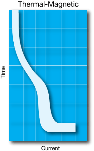
Figure 1: Circuit breaker technology characteristic performance.
(Source: E-T-A Circuit Breakers)
Derating Factors
The specifications of a circuit breaker are only valid under the conditions quoted in the data sheet; a frequency of 60 Hz in an open-air environment at 40 C ambient, for example.
If the real-world conditions differ from those under which the specifications were derived, derating factors must be applied.
For example, circuit breakers with uncompensated thermal-tripping elements have a tripping-current level that depends on the surrounding temperature.
If the circuit breaker is installed in an enclosure, or in a hot location such a boiler room, the current required to trip the circuit breaker on overload will be reduced; the reverse applies at low temperatures.
Similarly, operation at higher or lower frequencies than specified may also require modification of the specification.
On the one hand, eddy currents and iron losses at the higher frequency cause greater heating within the thermal-trip components, requiring the breaker to be derated.
At the low end, even DC operation can cause issues with extinguishing the arc that occurs when the contacts are separated in high-current applications.
| Ambient Temperature |
Multiplication Factor (approximate values) |
|
| ℃ |
℉ |
|
| -20 |
-4 |
0.76 |
| -10 |
+14 |
0.84 |
| 0 |
+32 |
0.92 |
| +23 |
+73.4 |
1.00 |
| +40 |
+104 |
1.08 |
| +50 |
+122 |
1.16 |
| +60 |
+140 |
1.24 |
Figure 2: Typical temperature-derating table. (Source: E-T-A Circuit Breakers)
In general, any unusual operating conditions may require modification of data sheet parameters or special design provisions if the circuit breaker is to perform as expected. In addition to those already discussed, such conditions may include corrosion, moisture, mechanical shock and vibration, altitude, and perhaps even mounting position. Circuit breaker manufacturers provide derating tables and operating guidelines to help you in this task. When in doubt, consult the experts at the factory.
Packaging
Circuit breakers come in a variety of sizes and mounting configurations for use on printed circuit boards, racks, and panels, all the way up to highly specialized installations for high-voltage electrical grid use.
Standards and Safety Agencies
Since circuit breakers perform a safety-related function, there are numerous standards issued by the various regulatory agencies. Some of the key ones are shown in Table 2. In addition, many applications—notably aerospace, automotive, and military—have their own testing and qualification requirements.
| Standard |
Covers |
| UL 489 |
Molded-Case Circuit Breakers, Molded-Case Switches and Circuit Breaker Encolsures |
| UL 1077 |
Supplementary Protectors for use in Electrical Equipment |
| UL 60950-1 |
Information Technology Equipment: General Requirements |
| NFPA 70 |
National Electrical Code (USA) |
| CSA22.2 |
National Electrical Code (Canada) |
| BS7671 |
National Electrical Code (UK) |
| IEC 60364 |
Electrical Installations for Buildings (EU) |
| IEC 60947-2 |
Circuit Breakers for Industrial Applications |
| IEC 60898-1 |
AC low-voltage circuit breakers |
| IEC 60934 | Circuit brekers for household applications including appliances |
Table 2: Some applicable circuit breaker regulatory standards. (Source: EEWordsmith)
Step-by-Step Selection Procedure
Now that we’ve reviewed the technology and some of the relevant design issues, follow the procedure outlined below to make sure you choose the best circuit protection solution for your design. First of all, make sure you list all of the required features and key parameters. Many manufacturers have interactive selection guides to help you narrow down the choices; it is recommended to consult their websites.
Step 1: Basic Electrical Parameters
- What is the voltage? Is it AC or DC? If AC, what frequency?
- What is the normal load current? Trip current?
- Number of poles and type—normally open (N/O) or normally closed (N/C)?
- Are any electrically separate auxiliary contacts needed? N/O or N/C?
- Required trip characteristic (see time/current curves above)
Step 2: Other Required Features
- Mechanical form factor (e.g. DIN rail, panel mount, standalone, etc.), or size constraint?
- Connection method? (e.g. blade, stud or screw terminals, round connectors, or solder pins)
- Additional features required? (e.g., a manual trip, manual or automatic reset, arc-fault detection)
Step 3: Operational Considerations
- Environmental conditions (maximum operating temperature, shock, vibration, altitude, corrosion, ionizing radiation, etc.) \
- Required safety approvals
- Industry-specific requirements (e.g. automotive, aviation, medical, hazardous operation, MIL STD, etc.)
Design Example
To illustrate the process, here’s a real-world design example.
The customer wanted to replace an existing fuse-block assembly that protected field I/O devices in a demanding industrial application.
Previously, a large variety of fuses had been used to meet both catastrophic short-circuit and overload protection needs, including both slow-blow (delay) and fast-acting types.
Basic Electrical Parameters:
- Operating Voltage: 24 VDC
- Normal load current: 10 @ 5 A each
- Number of poles and type: single pole
- Required trip characteristic: 100 ms trip time (approximately) at 3 times rated current to replicate performance of fuses
Other Required Features
- Mechanical form factor: PCB mount, small size (approximately 1 inch by 1 inch)
- Connection method: solder terminals
- Additional features required: provide indication of tripped state (auxiliary contact/alarm); switchable; resettable
Operational Considerations
- Environmental conditions: high shock and vibration specifications (seismic testing is part of the customer’s approval process)
- Enclosed cabinet installation with temperature excursions
Selection Process
Several circuit breaker technologies can meet the aforementioned electrical requirements; the initial solution utilized a fast-acting thermal (TO) miniature circuit breaker.
Temperature-derating factors were applied, but during testing, the thermal technology had too many nuisance trips within the allowable temperature window, ruling it out as a possible solution.
The next step was to move to a technology immune to the swing in temperature of the cabinet environment, but which could disconnect in the same amount of time as a standard fuse; in other words, a purely magnetic (MO) solution.
The 808 product family was a good fit for the application as it’s magnetic; single-pole; includes indications via a discrete signal and an LED; is designed to meet UL60950-1, CE, and CSA standards; operates over a wide -30º C to +70º C range; and is mounted on a
symmetrical DIN rail that can be plugged into a PCB.
The result was a very satisfied customer!
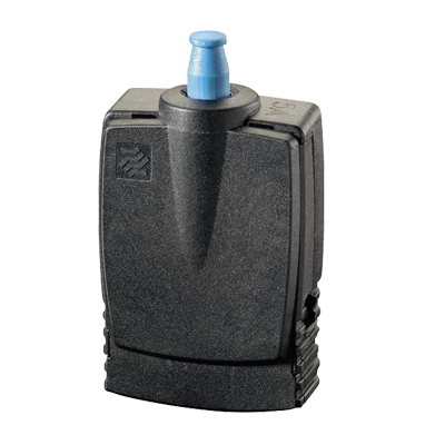
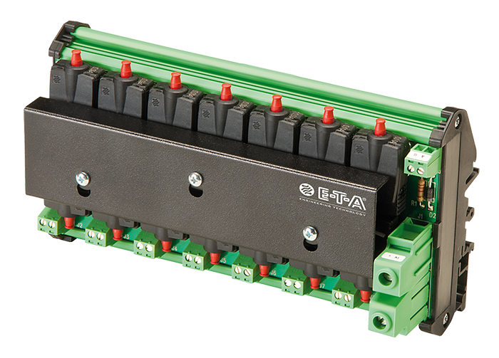
Figure 3: Single 808 circuit breaker and DIN installation. (Source: E-T-A Circuit Breakers)
There are many potential options when picking a circuit breaker for your application. A systematic selection procedure will help you make the right choice.
Want more information on selecting the right circuit breaker?
|
Have a question? E-T-A is active in more than 60 countries - with 6 production facilities and 12 subsidiaries. This provides customers with convenient and local access worldwide to E-T-A products and services. |