Improve Plant Production by Addressing 24VDC Switch-Mode Power Supply Issues
For most industries, the accepted norm for unplanned downtime is 5% of operating time, which represents a direct, significant loss of revenue and therefore profit. But have you ever stopped to consider the true cost of downtime?
How DC Power Supplies Respond to Overloads
 In a simple transformer-based power supply, a current overload will cause a gradual drop in
voltage output (P=U x I).
For example, at two times nominal current, the power supply will provide only half the normal voltage (See Figure 1).
A voltage drop may disable control components powered by the supply, which typically require at least 18 volts to operate.
In a simple transformer-based power supply, a current overload will cause a gradual drop in
voltage output (P=U x I).
For example, at two times nominal current, the power supply will provide only half the normal voltage (See Figure 1).
A voltage drop may disable control components powered by the supply, which typically require at least 18 volts to operate.

Switch-mode power supplies, on the other hand, are designed to quickly shut down when the total load current reaches 110% of nominal current. This is a feature manufacturers have designed into their products as a way to protect the power supply. The power curve of a switch-mode power supply is therefore very different (See Figure 2). The protection that is built into a power supply usually is in the form of a quickly operating electronic switch. Most of the components under load have capacitive behavior when switching on. Current in-rush could easily exceed the range of nominal current, which can cause the power supply to shut down. Switch-mode power supply manufacturers design power supplies to withstand this. If the overload condition is still present, the power supply will repeatedly try to power up and then immediately shut down - commonly known as a “hiccup”.
Adding Selective Circuit Protection
If a power supply is supplying multiple circuits, an overload condition on just one circuit that is not removed quickly will cause the power supply to shut down or cause a voltage drop to all other connected circuits. To protect individual circuits from one power supply, the system designer often will place a thermal or thermal-magnetic circuit breaker between each individual circuit under load and the power supply.
Let’s look at the behavior of a typical 10 A 24 VDC transformer-based power supply. For the sake of discussion, let’s say it has four circuits drawing 2 A each, for a baseload of 8 A. Each circuit is protected by a 2 A-rated circuit breaker. In the event that one of these circuits faults and draws 12 A, a typical 2 A thermal-magnetic circuit breaker might not operate fast enough to limit the voltage drop in the power supply. It can take up to five seconds for a standard delay thermal-magnetic circuit breaker to trip at six times its rating (See Figure 3).


In this example, the total current output of the power supply is 18 A (12 A+2 A+2 A+2 A). This means that the 10 A rated power supply must be able to deliver 18 A up to five seconds before a standard thermal-magnetic circuit breaker will trip. As shown in Figure 1, a transformer-based power supply is able to provide this power - although at a reduced voltage. After the circuit breaker trips, the voltage output again rises to 24 V in the remaining circuits, and the faulty circuit is indicated by the tripped circuit breaker. If the power supply output voltage drops below 18 V, all other circuits were disabled for up to five seconds before the circuit breaker tripped.
The Dilemma
Let’s look at the same scenario, but substitute a switch-mode power supply for the thermal-magnetic circuit breaker. As described above, the maximum current the switch-mode power supply will provide is 11 A (110% of nominal current).Therefore, an overload on any circuit that increases the total current to more than 11 A will cause the power supply to go into shutdown or hiccup mode. In the same example described above, the circuit breaker does not trip, the voltage drops to zero, and there is no easy way for engineers to tell which circuit is at fault.
One possible solution would be to use a fast-acting circuit breaker. In other words, use a thermal-magnetic circuit breaker that trips at only two-times rating, rather than six-times rating (See Figure 4). The drawback to this approach is that some control components create high, instantaneous inrush currents. While the inrush lasts only for a few milliseconds, a fast-acting circuit breaker can trip immediately at two times its rating, never able to stay closed during normal inrush current.
On one hand, if a standard delay thermal-magnetic circuit breaker is used, the circuit breaker will not operate at all, causing the power supply to shut down or go into hiccup mode. On the other hand, a fast-reacting circuit breaker might operate too quickly when the circuit is first turned on, unable to keep the circuit closed.
Conventional circuit breakers are effective in many applications, but because switch-mode DC power supplies are current-limiting, no conventional circuit breaker is able to perform both functions: limit the current to a safe value that avoids shutting down the power supply, and distinguish between a momentary inrush and a short circuit.
Electronic Circuit Protection
Now consider the use of a “smart” electronic switch to protect each DC circuit and provide more control over the flow of current and more ability to define those conditions that would trigger a disconnection.
While the basics of electronic circuit protection are not new, electronic switches are a new technology for circuit protection. Conventional circuit breakers use one of four technologies: thermal, thermal-magnetic, magnetic, and high performance. Circuit breakers using these technologies trip by the movement of a thermally activated bimetal or the movement of a solenoid. In contrast, DC electronic solid-state circuit protectors are transistor based - and all disconnection of a load is done electronically, rather than mechanically.
Smart Electronic Circuit Protector
In E-T-A’s estimation, a “smart” electronic circuit protector should tolerate a momentary inrush and at the same time limit the maximum current to no more than 1.8 times its rating with current ranges available from 1 to 12 A. It easily can be integrated into a power supply system to provide advanced circuit protection of factory automation components such as sensors, actuators, field bus couplers and controls.
 A smart device takes advantage of a technique known as “active current
limiting”.
In this approach, the circuit protector monitors the current and commands the device to limit the current to no more than 1.8 times its rating.
It is similar to a conventional circuit breaker, isolating the circuit when the current is too high for too long and disconnecting in 3-5 seconds if the current reaches 1.1-1.8 times its rating (See Figure 5).
The five-second response time is faster and safer than the response time of a typical thermal-magnetic circuit breaker, which could take 60 seconds to trip at two times its rating, and might not trip at all at 1.2 times its rating.
(See Figure 3). For short circuits the current is electronically shut down immediately, and the design should limit inrush currents of input capacitors when the circuit is first turned on.
It should provide electronic isolation of the circuit after a fault, or when the manual ON/OFF switch is actuated.
This sophisticated electronic switch technology would isolate the faulty circuit and aggressively protect control system components, while preserving factory uptime.
A smart device takes advantage of a technique known as “active current
limiting”.
In this approach, the circuit protector monitors the current and commands the device to limit the current to no more than 1.8 times its rating.
It is similar to a conventional circuit breaker, isolating the circuit when the current is too high for too long and disconnecting in 3-5 seconds if the current reaches 1.1-1.8 times its rating (See Figure 5).
The five-second response time is faster and safer than the response time of a typical thermal-magnetic circuit breaker, which could take 60 seconds to trip at two times its rating, and might not trip at all at 1.2 times its rating.
(See Figure 3). For short circuits the current is electronically shut down immediately, and the design should limit inrush currents of input capacitors when the circuit is first turned on.
It should provide electronic isolation of the circuit after a fault, or when the manual ON/OFF switch is actuated.
This sophisticated electronic switch technology would isolate the faulty circuit and aggressively protect control system components, while preserving factory uptime.
When an overcurrent condition occurs, the device should be resettable by either actuating the ON/OFF switch or be remotely resettable at a discrete or group level. Remote reset can be performed by a low-voltage signal to the device, which can be a significant advantage in certain environments such as aseptic clean rooms where access to control cabinets might be restricted.
Real-World Application
Engineers for an automaker knew they had a problem. Every time a fault of overload occurred in a single circuit, all other control components connected to the same 24 VDC switch-mode power supply disconnected causing widespread manufacturing disruption. The automaker calculated the cost of downtime for an assembly line was $1000’s per minute. What’s more, as the power supply tried to recover from the overload, it would often go into “hiccup” mode, quickly cycling on and off. Hiccuping or stalled equipment causes scrap and jeopardizes the safety of workers.
To solve the problem, factory engineers worked with E-T-A Circuit Breakers, a leading manufacturer of circuit protection devices for equipment. The basic idea was to add a circuit breaker between the power supply and each individual circuit. In the event of an overload in a single circuit, this method eliminates the shut down of power output to all connected circuits. However, the team soon discovered that because of the design of switch-mode power supplies, any solution would be outside the capabilities of conventional circuit breaker technology. E-T-A engineers decided to use a proprietary electronic technology to develop a new class of circuit protectors that operate as described above.
Cost Savings Realized
E-T-A’s ESX10-T is the first product to allow selective protection of equipment connected to a 24 VDC switch-mode power supply while avoiding nuisance tripping and costly power supply shutdowns. Fault status is clearly indicated via a multi-colored LED. All ESX10-T models have an auxiliary contact that also can provide a signal to a programmable logic controller or factory equipment software, so the line or process can safely shut down or remain in use in the event of a fault.

Want to learn more about E-T-A's products for the automation industry?
Complete the form below and we will contact you shortly.
Featured ProductESX10-T Class I, Div 2 Approved Electronic Circuit Protector 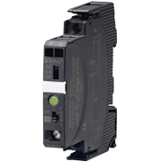 |